Installing the Software
There ist no need to flash the Arduino which is located on the FabScan PI HAT. It will be flashed automatically with the current firmware version after the server is started.
Installation with FabScanPi Image (recommended)
The fastest way to start working with FabScan PI is to use the FabScan PI Raspbian Image.
For the installation you will need the following things:
- A computer with integrated or connected card reader
- A Micro-SD card with at least capacity of 8 GB
- A software to format the SD card (e.g. SD-Formatter)
- A software to install the image on the SD card (e.g. Win32DiskImager)
- The latest FabScan PI Raspbian image
Download the SD-Formatter an the Win32Disk image software and install them on your computer. Tip: During the installation takes place you can already download and unzip the latest FabScan PI image and save some time. In the end you should have a file with .img extension.
Now insert the Micro-SD card into the card reader which is connected with your computer.
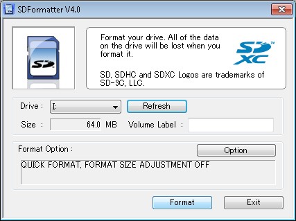
Start the SD-Formatter software and select the correct device letter. Double-check that because otherwise there is a risk of formatting another drive. Note: The displayed size of the selected card my vary from the physical size. This is because of an old image which is already installed on the card.
Click on the "Format" button to format the selected SD card.
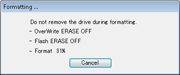
When the formatting process is completed an information window will pop-up. Leave the card in the reader.
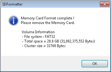
Exit the SD-Formatter and start the Win32DiskImager for transferring the image on the freshly formatted card.
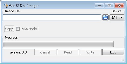
Select same device as before in the SD-Formatter software. Click on the folder icon and select the image file in your file system. Normally it should be in your browser's download folder. Make sure to unzip it first to get the image with .img extension.
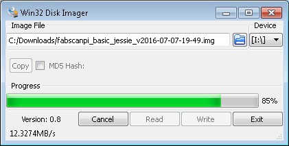
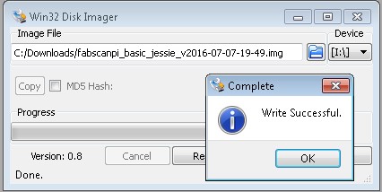
Click on the "Write" button and the installation process will begin to start. When it's finished you will be informed by a pop-up. Click on the "exit" button to close Win32DiskImager.
Now your SD-Card is ready to be put into the card slot of your FabScanPi.
After the image is flashed and the Raspberry Pi is up and running follow the instructions in the Usage section
Installing with fresh Raspbian and packages
This description assumes that you have a SD card with a fresh Raspbian image on it.
First add the fabscan repository to your source list.
echo "deb http://archive.fabscan.org/ jessie main" >> /etc/apt/sources.list
Then add the FabScan PI repository key to your key chain.
wget http://archive.fabscan.org/fabscan.public.key -O - | sudo apt-key add -
Update the package list.
apt-get update
Finish the installation with the needed packages.
apt-get install fabscanpi-server python-opencv-tbb libtbb2 python-pil python-serial python-pykka python-picamera avrdude python-semver python-scipy
The FabScan PI server can be started with
sudo /etc/init.d/fabscanpi-server start
Read Usage section for the next steps.
Build your own image of FabScan Pi
The image can be build with the FabScanPi Image build script. You will find more
information here
Installation: With Source Code
Dependencies
FabScan PI software depends on some python libraries. You need to install pyserial, pykka, opencv with tbb support and picamera. The easiest way to install all dependencies is to use debians package manager apt. Some of the packages, like opencv with tbb support and libtbb are not provided by the official raspbian mirrors. You need to add the fabscan repository to your apt source list.
Build Debian package Install dependencies
sudo apt-get install build-essential dpkg-dev debhelper devscripts fakeroot cdbs python-setuptools python-support
The package is build by calling
make deb
Afterwards the package can be installed by
dpkg -i fabscabpi-server<package-version>.deb
Updating the Software
Updates can be installed with debian's apt-get package manager. Log in via ssh and check/install updates with the following command.
sudo apt-get update && sudo apt-get dist-upgrade
Software User Manual
FabScan Pi is tested on:
| Browser | OS | Versions |
|---|---|---|
| OSX, Windows | 47.0.2526.106 (64-bit), 58.0.3029.110 (64-bit) | |
| OSX, Windows | 43.0.4, 53.0.3 (64-Bit) , 54.0 (32bit) | |
| OSX | Version 9.1.1 (11601.6.17) |
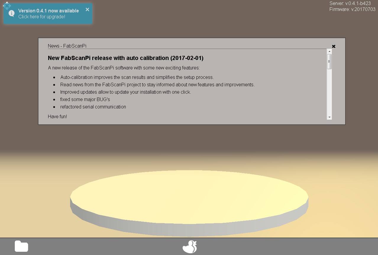
- By default the FabScanPi server binds to all interfaces on port 8080. Pointing your browser to http://ip-of-your-raspberry-pi:8080 will open the user interface.
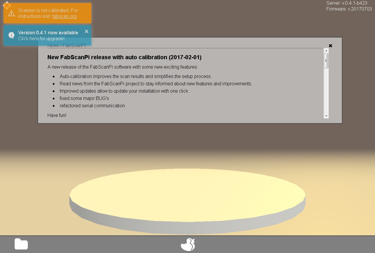
If your FabScanPi has access to the internet an information window with the latest project news will pop-up. You can close it by left-clicking on the black x in the upper right corner of the grey info window. If there is a new software version available you will see a note in the upper left corner:
Before you proceed with the calibration and your first scan please check a few things to ensure your FabScanPi is working properly:
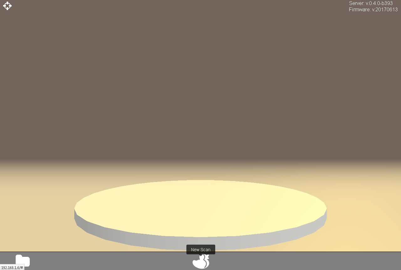
- Click on the duck icon (New Scan) to enter the scan menu.
- Now the turntable should turn clockwise in a constant smooth manner.
- The laser must be on and needs to be adjusted vertically and to cross the center of the turntable. You will have to do the adjustment by hand because the servo / stepper support for the laser has not been implemented yet.
- Check if you can see a small video preview in the lower left corner of the scan menu. Maybe there is only a turning hour glass visible. That is a known problem of some browsers but will have not effect the scanner's function.
- Click on the X (Cancel) to get back to the main menu.
Before you can start with your first scans you must perform a calibration. That is necessary because every Scanner housing is a bit different. By calibrating your scanner the software will get the exact parameters of your FabScanPi. You will have to do the calibration only once, the gathered data will be stored. But we recommend to do a calibration every time when the FabScanPi has been shipped, modified or when the scan results look distorted.
NOTE: Only after finishing the calibration successfully you will have good scan results .
The calibration will be done by scanning an calibration sheet with a specific pattern which must be placed on the turntable. The pattern must face the camera:
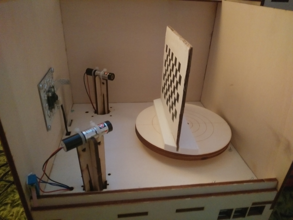 NOTICE: The second laser in the image is not supported by the software yet. This will be a feature available within the next release.
Option 1: You can can build your own calibration tool from cardboard. Print the calibration sheet onto paper and glue it to cardboard. Build a stand of another piece of cardboard. Maybe you have to fix the calibration sheet on the turntable by using some adhesive tape.
Option 2: You have an 3D-printer available and can print out our calibration sheet holder. There's also a different calibration sheet for external holder use.
INFO: To get a perfectly flat and stable surface glue the calibration sheet on a piece of thick pcb (printed circuit board).
Download calibration mount and sheet!
Version V1 and V2 have the same size. Both will fit. But V2 is more printer friendly.
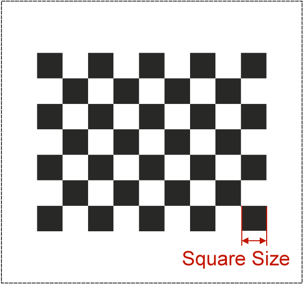
Note: Please check if your print of the calibration sheet has the correct scale. Each black square should have the same side length as stated on the calibration sheet (e.g.11 mm (1,1 cm). If the size is not correct please correct the parameter "pattern square size" in the configuration file.
You can find all details in the chapter "How to Edit the Config File".
Place the calibration sheet on the turntable facing the camera.
Please close the box to avoid external light sources to impact the calibration process. Start your browser and call http://ip-of-your-raspberry-pi:8080 which will open the user interface.
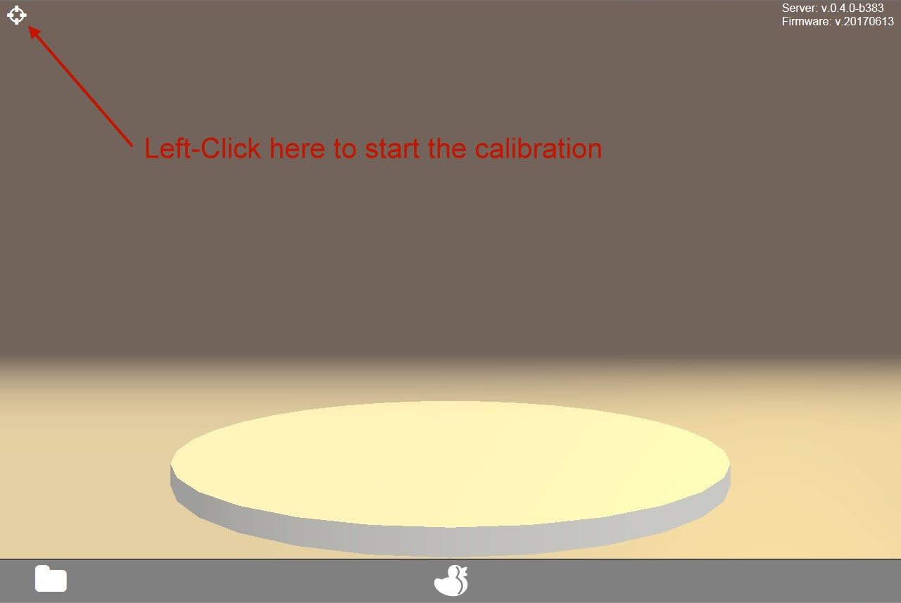
When you start your FabScanPi for the first time you will see an information in the upper left corner that you have to perform a calibration.
Start the calibration procedure by clicking on the gun sight icon in the very upper left corner.
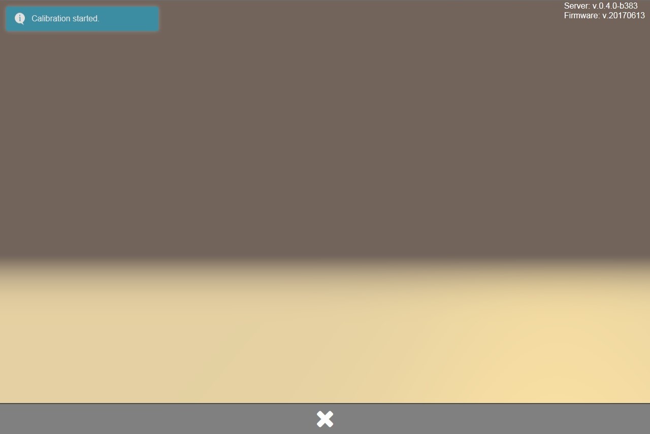
An information "Calibration started" will be displayed in the upper left corner.
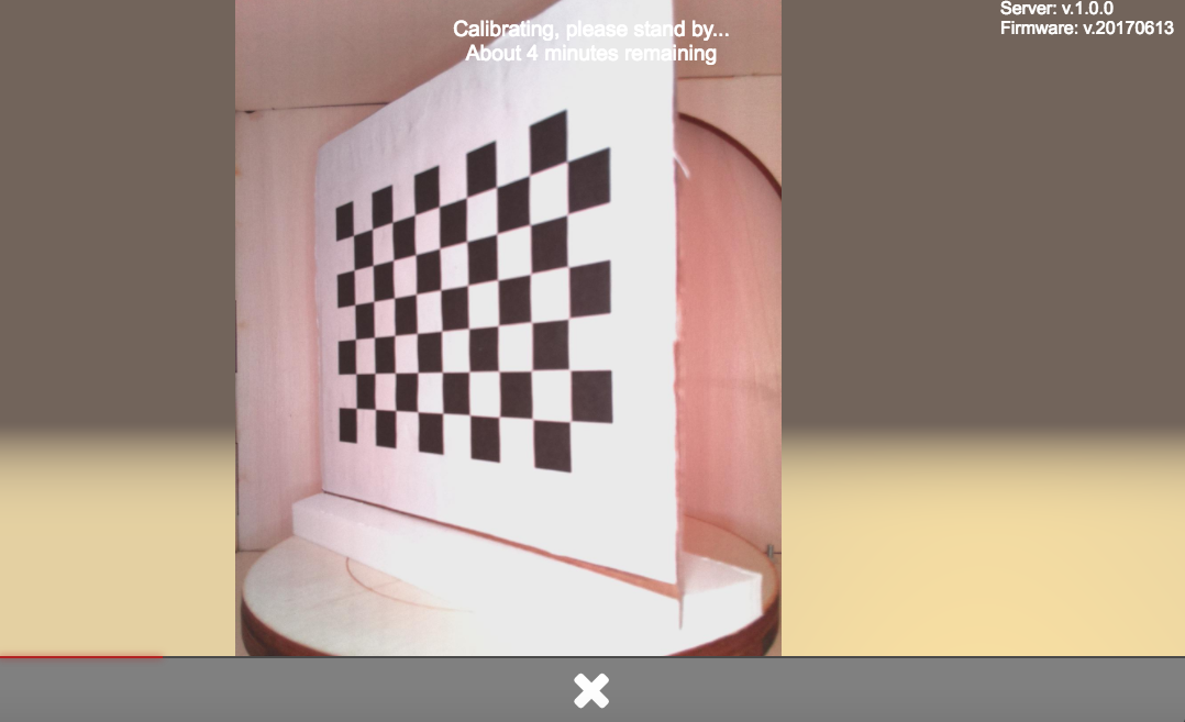
The calibration may need several minutes. During the calibration an information about the remaining time is displayed.
When the calibration was finished successfully another notification will appear for a short time in the upper left corner.
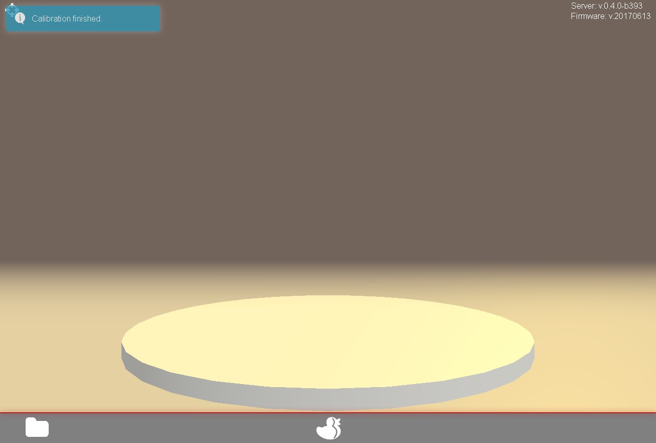
Now you can remove the calibration pattern sheet from the turntable and start your first scan.
NOTE: If your scan results look not like they should, probably distorted or skewed please check the calibration data in the configuration file. You can find details about the different relevant parameters in the Config File Values section of this documentation.
Note: The current settings are only persistent as long as the pi is up and running. The settings are saved with the scan data after a successful scan. They can be loaded to scan another object with the same settings. E.g. an object what consists of the same material, color etc.
- Click on the duckling-symbol to open the scan menu.
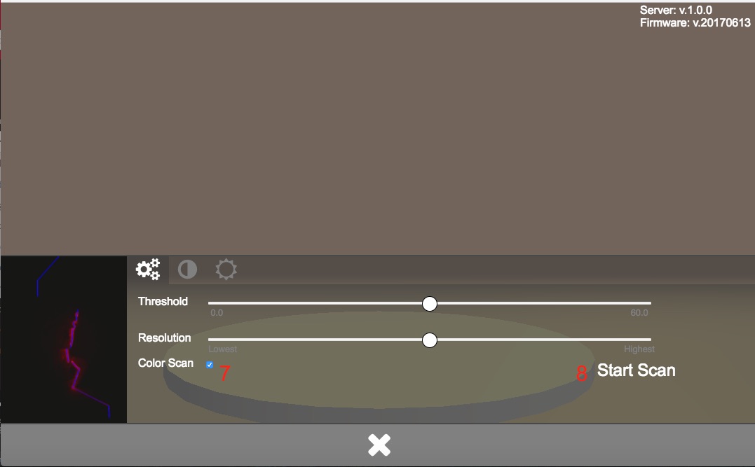
- The threshold-slider (6) can be used to adjust the sensitivity of the captured data. Select the scan quality by using the other slider (7). Note: The better the scan the longer is the required capture time. Sometimes it is better to start with a low resolution to control the selected settings result. If the result is nice you can perform a higher resolution scan with the same settings.
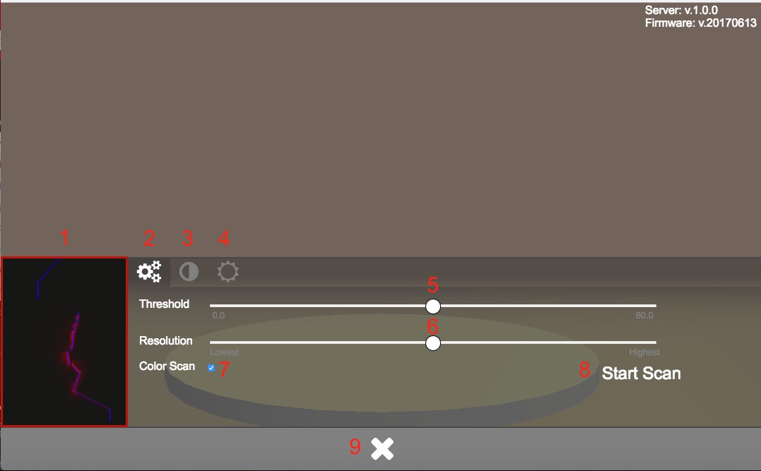
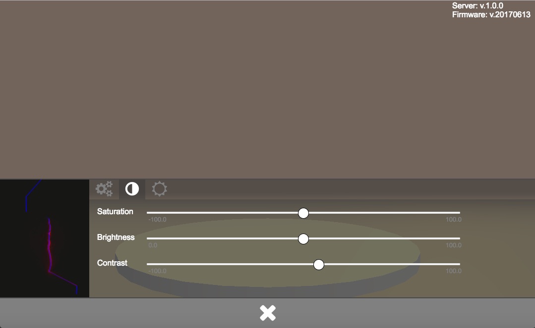
By clicking on the contrast-icon (3) you will get access to the camera settings menu. For adjusting the camera presets three sliders for saturation, brightness and contrast are available.
Click on the light-symbol (4) to get access to the lighting menu.
Here you can use the sliders to change the brightness and color of the (optional) light source. When all three sliders are at the very left end the light is off. Watch the preview in the lower left corner of the menu.
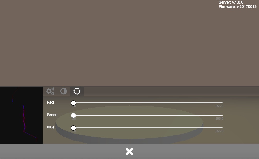
Note: The setting in the lighting menu will only cause an effect if an optional WS2812-compatible light source (e.g. Adafruit NeoPixel LED-Ring or FabScanPi-Camera-Holder) is installed.
Click on the arrows-and-circle symbol (5) to get access to the alignment menu.
- Make sure your FabScanPi is switched on, an object is placed on the turntable and the lid / the optional laser safety switch is closed.
- Open the web-interface as described in chapter Getting Started.
- Click on the duckling-symbol to open the scan menu.
Note: If you do not have installed a light source you should perform a monochrome scan.
- Adjust the scan preset values to your needs as described in chapter Presets.
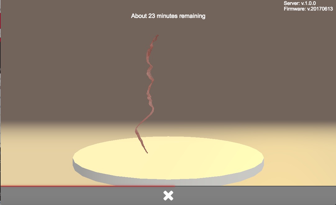
- Click on .Start Scan. to initiate the process A starting message will be displayed. Now the texture will be processed.
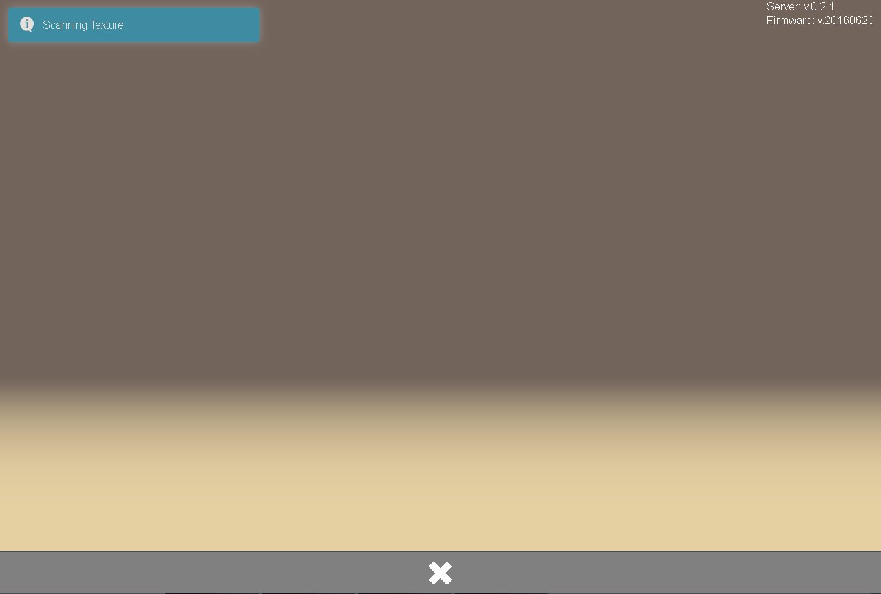
The latest photo will be displayed during the capturing process.
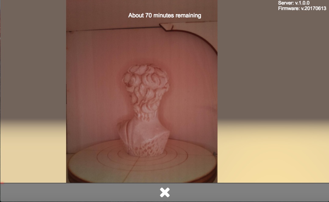
When the texture has been captured (progress bar at 50 percent) the actual scan is initiated. A notification is displayed.
A notification will be displayed when the scan is completed / file is saved.
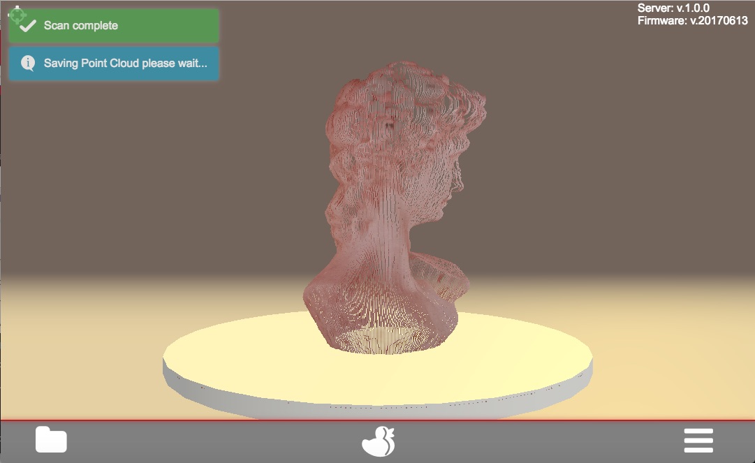
- You can now check, download or delete the scan-data.
- Make sure your FabScanPi is switched on, an object is placed on the turntable and the lid / the optional laser safety switch is closed.
- Open the web-interface as described in chapter Getting Started.
- Click on the duckling-symbol to open the scan menu.
- Adjust the scan preset values to your needs as described in chapter Presets.
- Uncheck the color-scan option (8)
- Click on .Start Scan. to initiate the process A starting message will be displayed and the scan process is started.
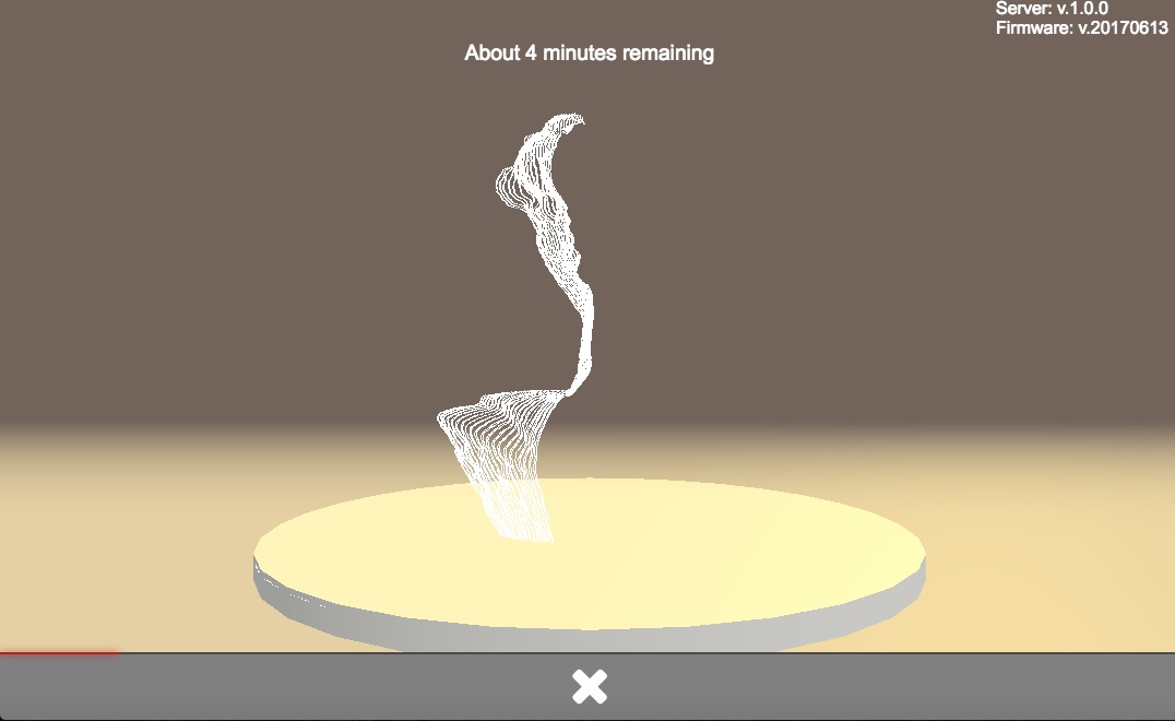
When the scan is completed / file is saved a notification will be displayed.
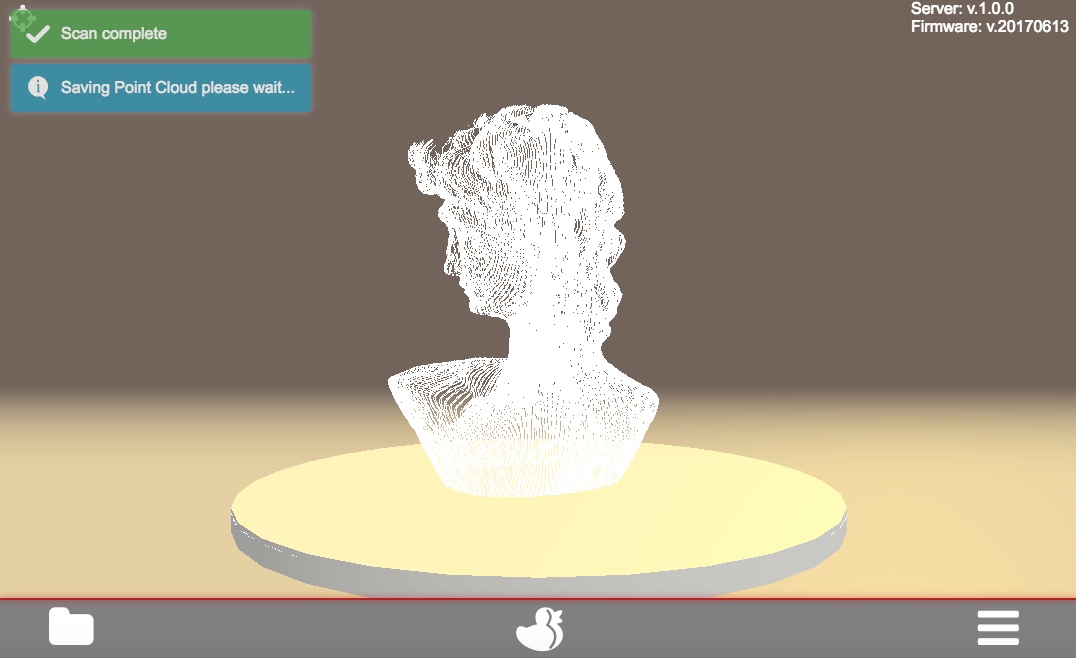
- You can now check, download or delete the scan-data.
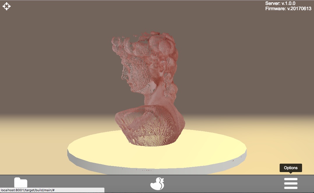
The FabScanPi software includes a feature to convert a scan into a mesh-file. This mesh-file can be used for 3D-printing. Note: To generate a mesh-file a scan must have been performed. It is also possible to load a scan-file which has been saved previously.
-
Click on the options icon to open the options menu.
-
The options menu will open and you can see the index card of the loaded file.
-
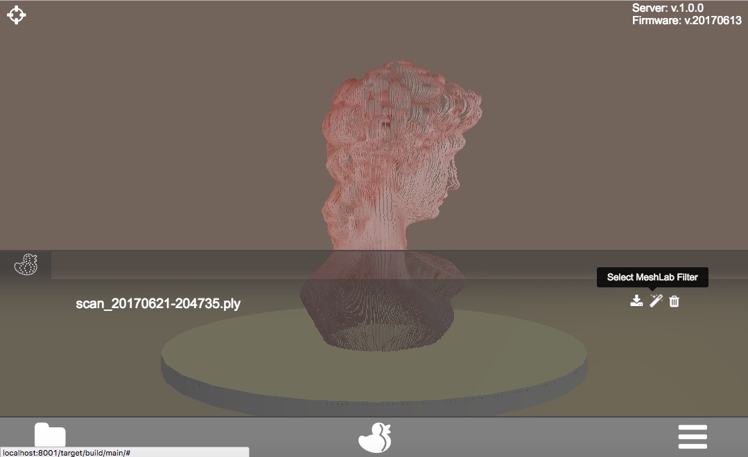
Click on the magic wand icon to open the menu for the MeshLab filter.
-
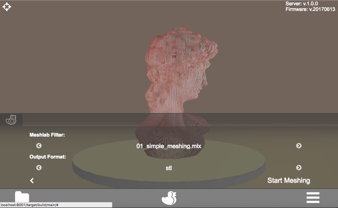
Now select one of the Meshlab filters and the file format for the future mesh file.
-
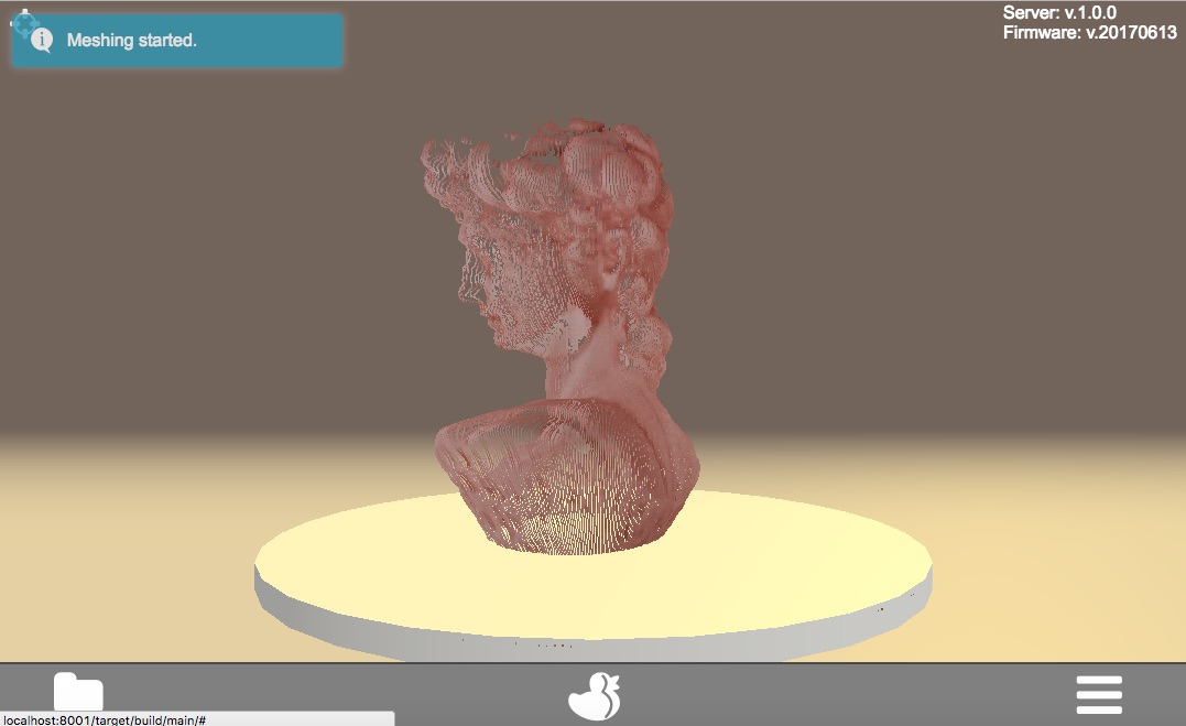
Click on "Start Meshing" to activate the conversion process.
The conversion starts and the main menu appears. A notification is displayed as well.
Note: Depending on the size and complexity of the scan file as well as the type of selected filter the conversion process may take some time.
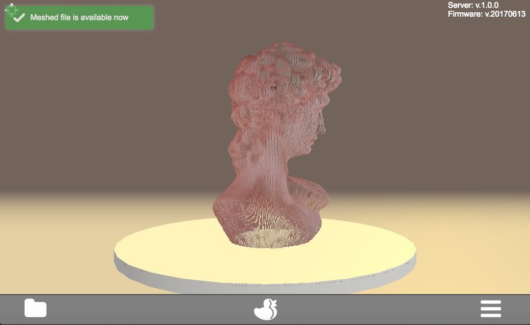
When the mesh-file is available a notification is displayed.
-
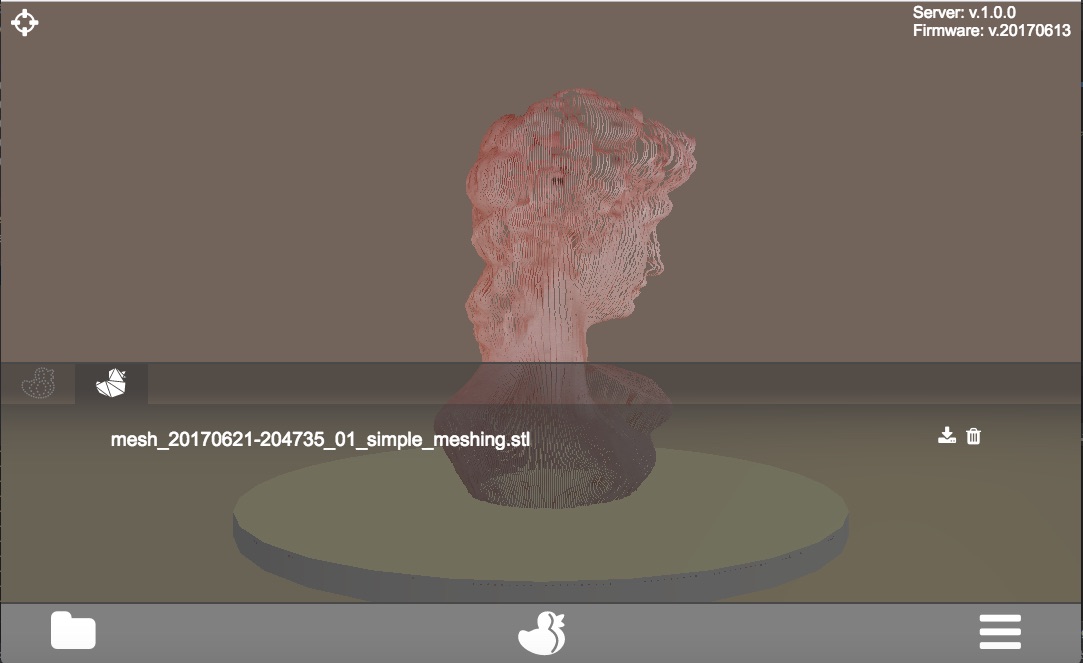
Again open the options menu. Another index card for the mesh-file has been added.
-
Click on the mesh-file index card.
-
You can now click on the download-icon to download the mesh-file to your computer or click on the trashbasket icon to delete the mesh-file.
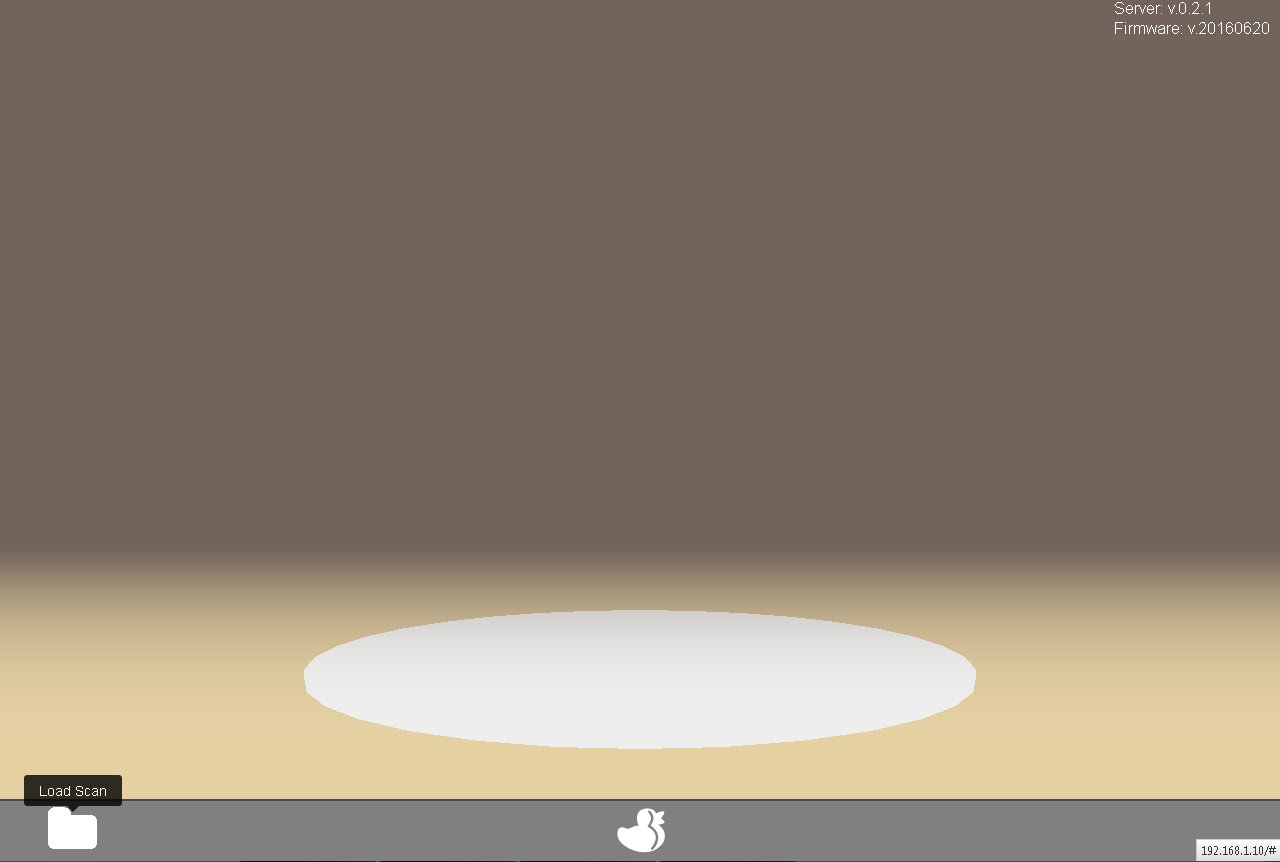
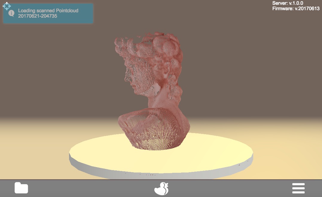
A scan result which has been saved to the FabScanPi memory previously can be reloaded. Go to the main menu and click on the folder-icon at the left side of the menu bar.
- Scroll through the displayed file inventory and click on the icon of the wanted file.
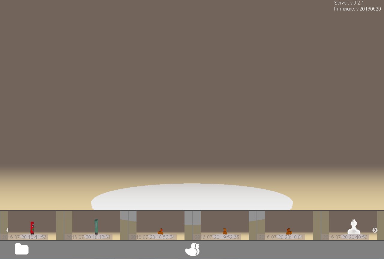
Now the selected file will be loaded which may need some time. After the loading process is finished a notification will be displayed.
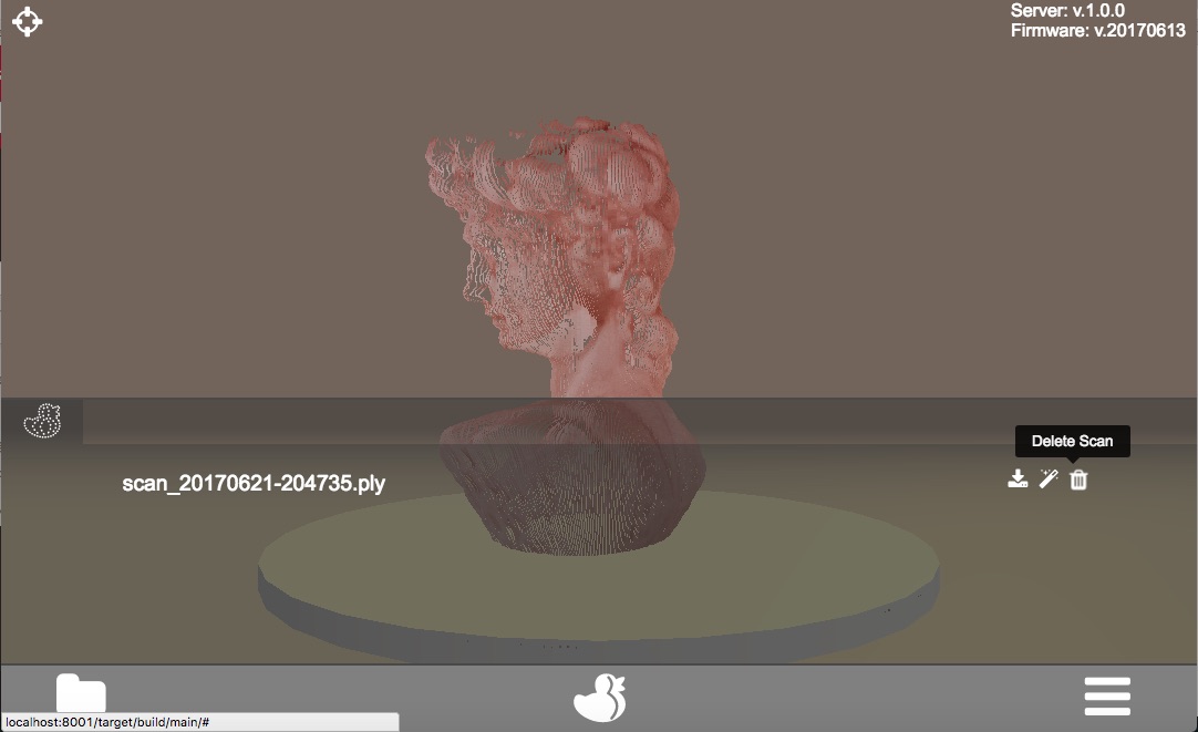
Delete a scan-file
A scan result which has been saved to the FabScanPi memory previously can be deleted. To do that it must be loaded and displayed on the virtual turntable in the main menu.
-Click on the options-icon on the right side of the menu bar.
Click on the wastebasket-icon to delete the scan-file. NOTE: By deleting a scan file the corresponding mesh file (if available) will be deleted instantly.
Delete a mesh-file
Note: If a mesh file is available a second slide for the mesh file will be displayed.
By selecting the mesh slide and clicking on the wastebasket-icon the mesh-file can be deleted separately.
- Download Files It is possible to download generated files (either scan- or mesh-files) from the FabScanPi via the web-based user interface.
Download a scan-file Note: Before you can download a file it must be loaded and displayed on the virtual turntable in the main menu.
-
Go to the main menu.
-
Click on the options-icon on the right side of the menu bar.
-
Click on the download-icon to download the mesh-file
-
A download message (depending on the used web-browser) will be displayed
Download a mesh-file
Note: If a mesh file is available a second slide for the mesh file will be displayed.
- Select the mesh slide
- Click on the download-icon to download the mesh-file
- A download message (depending on the used web-browser) will be displayed
Config File Values
A configuration file can be found in /etc/fabscanpi/default.config.json. The content of this file is in JSON format and can be edited with an editor of your choice (e.g. nano). Be careful and don't miss brackets. JSON is really sensitive in it's format.
NOTE: The following listing snippets are only examples and may deviate from the latest settings.
Folders
In this section you can change the scan output folder and the folder where the ui is located. If you don't know what you are doing, it is a good decision to keep this section untouched.
   "folders": {
        "www": "/usr/share/fabscanpi/",
        "scans": "/var/scans/"
    }
Laser
This section describes the laser stepper motor values. The rotation_steps value should be used for a laser angle change (not implemented yet).Steps defines how many steps the motor can do. In the default case the motor is set to 1/16 step mode. A motor with 200 steps per turn can then perform 3200 steps.
    "laser": {
        "steps": 3200,
        "numbers": 1,
        "rotation_steps": 5
    }
Scanner Calibration
In this section you can change the parameters of the configuration sheet. If your printout of the calibration sheet has not the exact scale you can adjust the parameters here instead of scaling the print.
NOTE: There is a new " 8x6 Calibration Pattern". If you are still using the old 9x6 Pattern you'll need to modify the columns value:
"scanner_type": "laserscanner", "calibration": {
"weight_matrix": [],
"dist_camera_matrix": [],
"pattern": {
"square_size": 11,
"rows": 6,
"columns": 8,
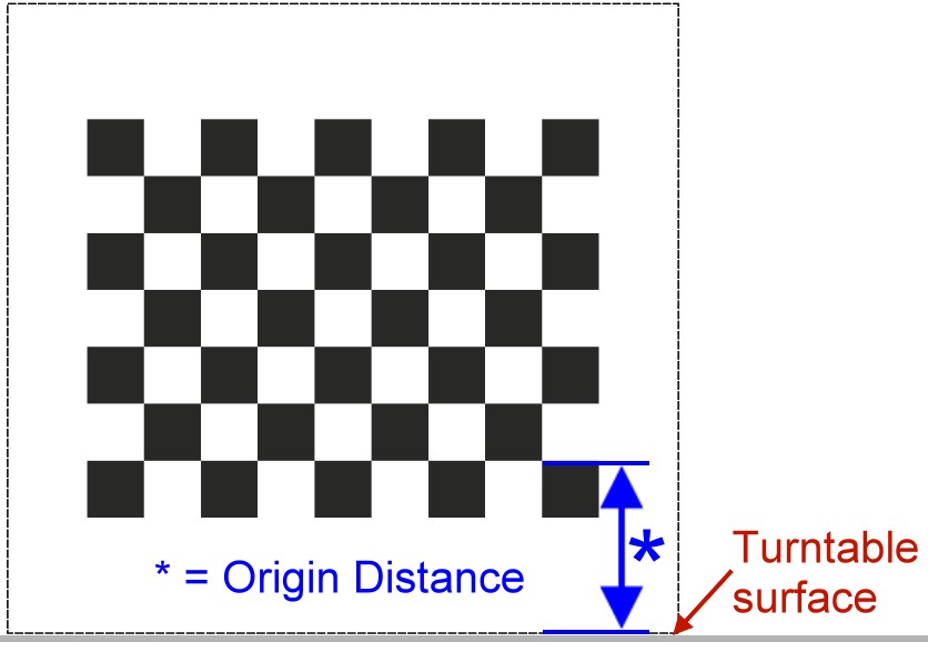
"origin_distance": 35
}
- Square Size is the side length of one black square in millimeters.
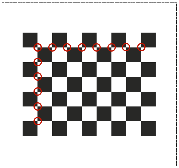
- Rows and Columns are the connection points of the black squares. The correct number is 8 for columns and 6 for rows :
- Origin Distance is the distance between turntable surface and the upper edge of the black squares in the row close to the turntable.
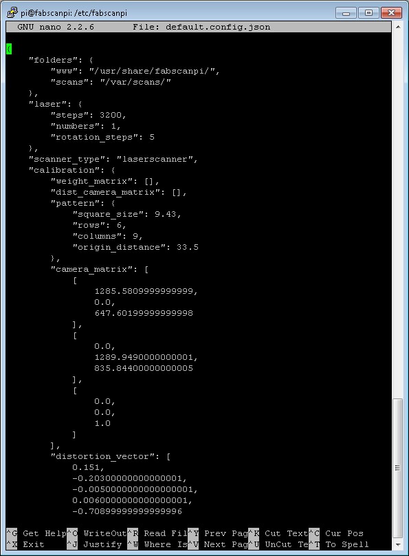
Scanner Calibration Values
In this section you can check the calibration parameters. Please make sure you have performed the auto-calibration before starting your first scan. Do not change these values manually. This values are generated by the autocalibration process.
        "camera_matrix": [
            [
                1285.5809999999999,
                0.0,
                647.60199999999998
            ],
            [
                0.0,
                1289.9490000000001,
                835.84400000000005
            ],
            [
                0.0,
                0.0,
                1.0
            ]
        ],
        "distortion_vector": [
            0.151,
            -0.20300000000000001,
            -0.0050000000000000001,
            0.0060000000000000001,
            -0.70899999999999996
        ],
        "laser_planes": [
            {
                "deviation": 0.052318819865,
                "distance": 137.366403938,
                "normal": [
                    0.56199451,
                    -0.01896656,
                    0.82692348
                ]
            }
        ],
        "platform_translation": [
            4.21176054e-03,
            4.26178340e+01,
            1.66114592e+02
        ],
        "platform_rotation": [
            [
                0.0,
                9.99977231e-01,
                6.74816764e-03
            ],
            [
                4.51612662e-02,
                6.74128255e-03,
                -9.98956964e-01
            ],
            [
                -0.99903697271524872,
                0.00030800546235732861,
                -0.043875189806843448
            ]
        ]
    }
Meshlab settings
In this section you can change the path for the converter which transforms the scanned pixel data into another format (e.g. .stl).
    "meshlab": {
        "path": "/usr/bin/"
    }
Table settings
In this section you can change the turntable settings. The radius of the turntable is in millimeters (mm). In the default case the motor is set to 1/16 step mode. A motor with 200 steps per turn can then perform 3200 steps. Radius is the radius of the turntable in millimeters (mm).
    "process_numbers": 4,
    "turntable": {
        "steps": 3200,
        "radius": 70
    }
Camera settings
Preview Resolution is the resolution value for the settings window. Resolution is the resolution for the picamera python module. You can have a look to the documentation of picamera. If you set this to other values please be sure what you are doing, not all resolutions are supportedby the picam. Some might lead to slower image capturing.
    "camera": {
        "resolution": {
            "width": 1640,
            "height": 1232
        },
        "preview_resolution": {
            "width": 240,
            "height": 320
        },
        "rotate": "True",
        "hflip": "True",
        "vflip": "False",
        "type": "PICAM"
    }
Serial
In this section you can set your port. By default this value is not set, because theFabScanPi Server software autodetcts the correct port. Some Arduino and compatible boards differ in the port name. The port can be set if you are not using an Arduino UNO or compatible Board. In case that your Arduino is not detected and you can see an error in the /var/log/fabscanpi/fabscan.logyou should add the "port" attribute to your config.
The autoflash option is True by default, that means that the firmware is flashed automatically to the Arduino or FabScanPi HAT. If you want to use a custom board e.g. sanguinololu, you can set thisto False and flash the Firmware manually to your board.
    "serial": {
        "baudrate": 115200,
        "autoflash": "True",
        "port": "/dev/ttyAMA0"
    }
Texture illumination
In this section you can change the pre-set brightness level of the LED-Ring during texture scan.
    "texture_illumination": 140
    }
How to Edit the Config File
Remote access to change the configuration settings
It is most likely that you don't have a monitor nor mouse and keyboard connected to your FabScanPi all the time. But maybe you need to make some changes to the config file from time to time and you don't want to connect the peripherals everytime.
This can be done via a remote PC which is connected to the same network.
Connecting as Windows User (Putty)
First of all you need to download the tiny program "PuTTY" from http://www.putty.org/.
PuTTY is a SSH client program which establishes the connection to your FabScanPi. There is no no graphic user interface -only a console which allows only the exchange of text. But that's enough to make some changes in the config file or to update your FabScanPi-Software.
You don't need to make an installation just put the putty.exe in a folder or your desktop. Of course you can start it directly from the download folder as well.
Now you must know the IP-address which has be assigned to your FabScanPi. It is the same address you're using to get access via the webbrowser (e.g. 192.168.1.8). Usually you can check the current IP-address in the user-interface of your web-router or cable modem.
Start Putty.exe and a window will pop up.
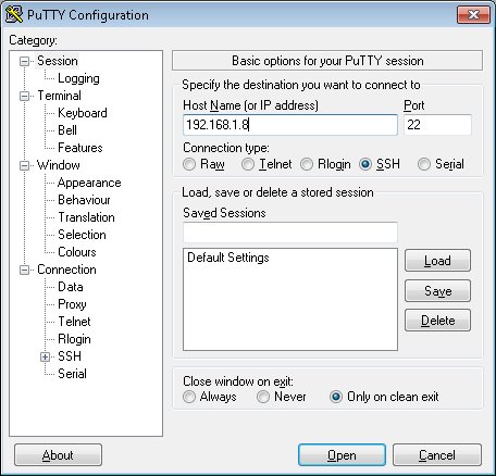
Type in your IP-address in the appropriate field and click on "OPEN".
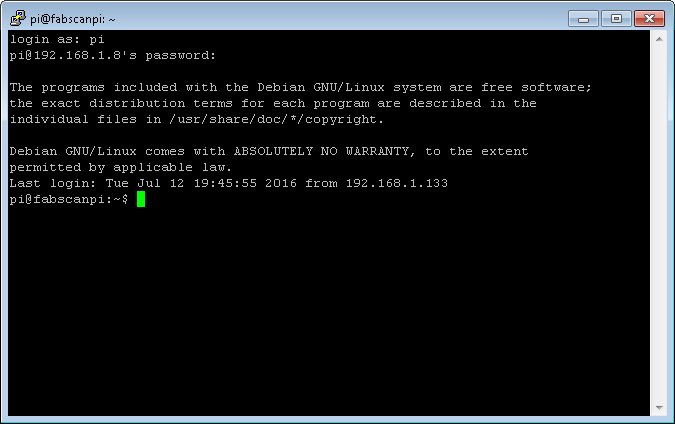
Now the console window opens and you must type in "pi" as login-name and "raspberry" as password (without the quotes). Now you should be able to see the login prompt (similar to the picture above).
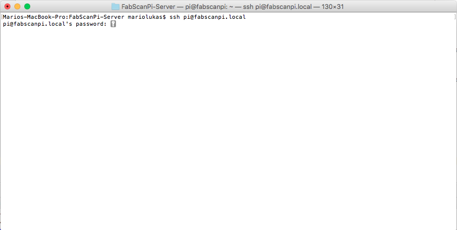
Connecting as Linux or OSX User (Terminal)
Linux users can open a Terminal and type "ssh pi@fabscanpi.local" ("sh pi@ip-address-of-you-pi"). Next you are asked for a password. Type in "raspberry" as password (without the quotes). The next steps are described with screenshots for Putty, but the workflow is the same once the connection is established.
Changing the config file.
The config file is in a different folder, so you must change into that folder by entering the command:
cd /etc/fabscanpi/
and press ENTER.
To view and modify the config file (default.config.json) you must open it with an editor and using administrator rights to be able to save the changes into the same file. The editor which is already installed is called nano. So type in:
sudo nano default.config.json
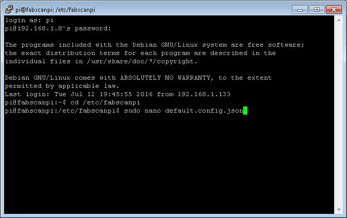
You have to enter the password "raspberry" (without the quotes) again, because you open the editor with administrator rights.
The nano-editor now displays the config-file and maybe you have to enlarge the window to have a better view.
Now you can perform the desired changes by using the keyboard. To navigate you have to use the up-, down-, left- and right-key.
If you finished your modification press you can save the file by pressing and holding CTRL and O (german keyboard: STRG and O). Press RETURN to confirm the filename.
Now you can exit the editor by pressing and holding CTRL and X (german keyboard: STRG and X).
For the changes to take effect you must restart your FabScanPi by typing in the command
sudo reboot
and ENTER.
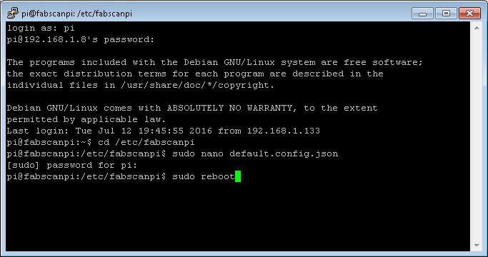
You can now close the PuTTY window.
The FabScanPi is rebooting and after a short time you can refresh your webbrowser and start using the FabScanPi with the new config settings.
Troubleshooting
Can not connect to Arduino. Is the Arduino connected to the USB port. Check the port in your fabscanpi-server configuration file. Try another port e.g. /dev/ttyUSB0. More information about changing the configuration can be found in "FabScan Pi Configuration" section.
Camera is not connected. Check the cable from the Raspberry Pi to the camera module. Be careful the cable can be very fragil. Try another camera application for checking camera functionality e.g. raspistill.
Setting up a WIFI connection
This description explains howto setup a wifi stick for raspbian. I prefer to use an EDIMAX dongle, it worked best for me. First plug in your wifi dongle and log in via ssh with password "raspberry" (without quotes):
ssh pi@<your-fabscanpi-ip>
First you have to activate the wifi option in your networking setup.
sudo nano /etc/network/interfaces
Uncomment the folling lines and save the changes.
auto wlan0
allow-hotplug wlan0
iface wlan0 inet dhcp
wpa-conf /etc/wpa_supplicant/wpa_supplicant.conf
iface default inet dhcp
Now restart your network adapters.
sudo /etc/init.d/networking restart
If you type sudo ifconfig there should be a wlan0 connection in the list.
Your fasbcanpi image is ready to go. The only things you have to do is open wpa_supplicant.conf and insert your wifi ssid and your wifi secret.
sudo nano /etc/wpa_supplicant/wpa_supplicant.conf
Save the file and try to connect to your wifi by typing the following command.
sudo ifup wlan0
In some cases you have to reboot the Raspberry Pi. Check if the wifi dongle's led is bliking. If you want to change your Raspberry Pi to a fix wifi IP address you have to change the interfaces file to get a static wifi connection.
sudo nano /etc/network/interfaces
Change the files content from
auto lo
iface lo inet loopback

allow-hotplug eth0
iface eth0 inet dhcp

auto wlan0
allow-hotplug wlan0
iface wlan0 inet dhcp
wpa-conf /etc/wpa_supplicant/wpa_supplicant.conf
iface default inet dhcp
to
auto lo
iface lo inet loopback

allow-hotplug eth0
iface eth0 inet dhcp

auto wlan0
allow-hotplug wlan0
iface wlan0 inet static
address <ip in your network>
netmask <your netmask>
gateway <your gateway>
wpa-conf /etc/wpa_supplicant/wpa_supplicant.conf
iface default inet dhcp
After you changed the file you can restart your network daemon.
sudo /etc/init.d/networking restart